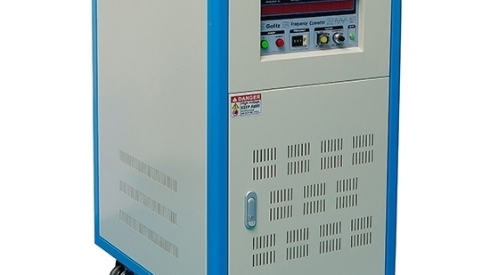
Advanced Frequency Converters: Engineering Principles and Applications in Power Systems

Frequency Converters, also known as Power Frequency Converters or Mains Converters, are critical power electronic systems designed to alter the frequency of an alternating current (AC) power source. Unlike simple motor drives, these sophisticated devices provide precise, independent control over both output frequency and voltage, delivering a pure sine wave to support a wide array of sensitive and specialized equipment across global industries.
1. Core Operational Principles and Topology
At its core, a frequency converter performs a double conversion process to achieve a clean and stable output, independent of input power quality.
1. Rectifier Stage (AC to DC): The input AC power (e.g., 50 Hz, 480V) is first converted to direct current (DC). Advanced models utilize an Insulated-Gate Bipolar Transistor (IGBT) based rectifier in conjunction with a DC choke. This active front end (AFE) technology minimizes harmonic distortion reflected back to the mains supply, ensuring compliance with standards like IEEE-519.
2. Inverter Stage (DC to AC): The smoothed DC bus is then inverted back to AC at the desired frequency and voltage. This is achieved through high-speed switching of IGBTs using Pulse Width Modulation (PWM) or more advanced techniques like Space Vector Modulation (SVM). The key differentiator from a standard Variable Frequency Drive (VFD) is the filtering and control logic that produces a pure sine wave output with low total harmonic distortion (THD), typically <3%.
2. Key Differentiator: Frequency Converter vs. Variable Frequency Drive (VFD)
While both devices change frequency, their applications and outputs are fundamentally different.
| Feature | Frequency Converter | Variable Frequency Drive (VFD) |
| :--- | :--- | :--- |
| Output Waveform | Pure Sine Wave | Pulse-Width Modulated (PWM) Square Wave |
| Control | Independent Voltage & Frequency (V/Hz) Control | Linked V/Hz Ratio (Volts per Hertz) |
| Primary Load | Universal: Sensitive Electronics, UPS, Lighting, Motors | AC Induction Motors Only |
| Design Goal | Power Conditioning & Compatibility | Motor Speed and Torque Control |
A Frequency Converter allows an operator to set, for example, 400 Hz at 115V or 50 Hz at 230V independently, providing the exact power profile required by the load. A VFD cannot decouple these parameters.
3. Critical Technical Specifications and Design Considerations
When specifying a frequency converter, engineers must evaluate several key parameters:
Output Power Rating (kVA/kW): Must account for inrush currents and the load's power factor.
Frequency Stability: High-precision oscillators ensure output frequency accuracy, crucial for synchronous systems and avionics.
Dynamic Response: The ability to maintain stable voltage and frequency under rapidly changing load conditions.
Efficiency: Modern IGBT-based converters can achieve efficiencies exceeding 95%, reducing operational costs and thermal load.
Protection Features: Comprehensive suites including overload, short-circuit, over-temperature, and under/over-voltage protection are standard.
4. Specialized Applications Requiring Precision Frequency Conversion
Aerospace and Defense (400 Hz Power): Aircraft and ground support equipment operate on 400 Hz power for reduced component weight and size. Frequency converters are essential for testing and powering this equipment from standard 50/60 Hz grids.
Manufacturing and Export: Allows equipment designed for one regional power standard (e.g., 60 Hz, 110V) to operate seamlessly in another (e.g., 50 Hz, 220V), eliminating the need for motor rewinding or separate machinery.
Research and Development (Variable Frequency Testing): Used to test the performance and durability of components like transformers, capacitors, and entire systems across a range of frequencies (e.g., 0 Hz/DC to 120 Hz or higher).
Marine and Offshore Vessels: Provide stable, conditioned power for sensitive navigation, communication, and control systems from the ship's variable-frequency generator sets.
5. The Criticality of the V/Hz Ratio in Motor Applications
While frequency converters can power any load, their use with motors requires careful consideration of the Volts-per-Hertz (V/Hz) ratio. The torque-producing capability of an AC induction motor is directly related to the magnetic flux in its core, which is maintained by a constant V/Hz ratio.
Synchronous Speed: `N_s = (120 × f) / P`
Constant V/Hz Principle: A motor rated for 460V at 60 Hz has a V/Hz ratio of 7.67. To maintain rated torque at 50 Hz, the voltage must be adjusted to `50 Hz × 7.67 V/Hz = 383.3V`.
A sophisticated frequency converter allows for programmable V/Hz curves, enabling optimal motor performance across its entire speed range while preventing magnetic saturation at low frequencies or insulation stress at high frequencies.
Conclusion
Frequency converters are indispensable tools in the globalized and technologically advanced industrial landscape. By providing clean, stable, and precisely controlled AC power, they bridge the gap between incompatible power systems, enable critical testing procedures, and ensure the reliable operation of high-value assets. Their advanced double-conversion architecture with pure sine wave output distinguishes them as a premium power conditioning solution, far surpassing the capabilities of basic motor drives.

Leave a comment